
3MF vs STL: keep units and print-project data in the handoff
Choose 3MF when a printing handoff needs explicit units, object structure or supported material and property data. Use a slicer project when the recipient also needs that application's print setup. STL remains useful when the receiving workflow requests a simple triangle mesh, provided you communicate units and print requirements separately. Neither format guarantees fidelity, interoperability or a more accurate physical print.
This guide concerns information carried from a model into a printing workflow. For exchanging CAD solids and understanding editable-history limits, read STEP vs STL. The downloadable comparison below holds the mesh geometry constant; it is not a controlled physical print test.
Choose what the recipient needs to reopen
- A mesh to slice from scratch: STL can be sufficient. Send the intended units, dimensions and revision alongside it. The recipient supplies the printer, material and slicing settings.
- A model with units and supported properties: a model-only 3MF can carry these in one package. Confirm which properties the exporting and receiving applications actually support.
- A prepared job to revisit: save a project in the originating slicer. A 3MF project can include application-specific settings and modifiers, but another slicer may not interpret them the same way.
Ask whether the recipient wants to choose their own print setup or reproduce yours. Sending a configured project without explaining that distinction can carry unwanted machine assumptions into the next step.
What 3MF can preserve that STL does not standardize
Units travel with a 3MF model
The 3MF Core Specification, section 3.4 defines a model unit attribute, with millimeter as the default. A producer can explicitly declare millimeters rather than leaving the reader to infer them. STL coordinates have no standardized unit declaration, so an 80-unit edge needs an external agreement that those units mean millimeters.
A unit field reduces ambiguity; it cannot correct geometry exported at the wrong scale. Measure a known dimension after import in either format. If the design is 80 mm long, check that the receiving application reports 80 mm before slicing, rather than accepting a preview that merely fits on screen.
Materials and properties require a supported mapping
3MF Core defines base-material resources and references that can assign properties to objects or triangles. Its material names express design intent and help map the model to actual printing materials. A material name does not certify a spool's composition, strength or processing temperature.
The distinction between appearance and manufacturing is important. Core section 5.1 says a base material's display color is for rendering, and producers must not assume it changes the printed part. Printed-color intent requires the appropriate material/property extension or another corresponding extension. A colored preview alone does not prove that filament slots, material regions or printer settings survived the handoff.
Check assignments in the receiving slicer and map them to the intended materials and extruders. The Library of Congress STL description documents STL's triangle-based surface representation and lack of standard color support. Binary STL color conventions exist, but incompatible conventions are not a reliable replacement for an agreed material workflow.
Objects and metadata can retain context
3MF supports object resources, components, build items and metadata such as the source application or a description. That structure can keep more context together than a bare STL surface. Optional metadata still depends on what the producer writes and what the consumer understands or preserves.
Core section 3.4.1 says consumers should ignore unrecognized metadata. Required extensions are different: an editor or manufacturing device that does not support an extension declared as required must not process that model file. A successful geometric import therefore does not establish that every property or project setting was retained.
Model-only 3MF is different from a vendor slicer project
A model-only 3MF contains model data for the next application to interpret. It need not include layer height, infill, supports or a printer profile. A slicer project uses the package to retain a particular application's working state. Both may end in .3mf, so the extension alone does not tell you what will load.
Prusa's project-saving documentation describes saving objects, settings, modifiers and their parameters as a 3MF project. Its export documentation distinguishes that operation from exporting the plate or individual models as STL. These are statements about that application's workflow, not promises that every other slicer will restore its project state.
Before opening a shared file, decide whether you want geometry only or the saved project settings. Use the receiving application's import options deliberately. For project reuse, record the slicer name and version, then inspect the printer profile, nozzle, material mapping and custom settings before generating machine instructions.
3MF Core 1.4 recommends descriptive endings such as .model.3mf and .project.3mf to clarify intent. Treat names as labels, not validation. A model package can still contain incomplete data; a project can still contain settings that are wrong for the recipient's machine. Neither kind guarantees interoperability or fidelity.
Does 3MF inherently print more accurately than STL?
No. For the triangle-mesh case considered here, packaging the same surface in 3MF does not add geometric detail. Converting a coarse STL to 3MF does not recover the original CAD curves or sharpen faceted holes. A meaningful geometry comparison must account for tessellation, coordinate precision, transforms and any repair performed during import.
Physical results also depend on slicing settings, printer calibration, material behavior and the manufacturing process. Preserving a setup can help another operator understand a job, but it cannot certify dimensional accuracy or strength. Inspect the sliced layers and measure the manufactured part against its actual acceptance requirements.
File size is a separate question. 3MF uses ZIP packaging, which allows compression, while project contents can add settings, thumbnails and other data. A smaller download does not prove a more accurate model, and a single pair of files cannot establish a universal size advantage.
Download a comparison with the same tessellation
The example is an author-defined 80 × 50 × 6 mm mounting plate with four diameter-5 mm through-holes. Their XY centers are (10,10), (70,10), (10,40) and (70,40). The native design has one solid, a box minimum corner at (0,0,0), and four cylinder cuts starting at z = -1 with height 8 mm.
These assets were generated from native schema-v1 design parameters through the existing geometry kernel. They demonstrate a deterministic construction and export workflow, not evidence that an AI prompt generated this model. The 3MF was prepared separately for this comparison from the exported mesh.
- Download the binary STL for a mesh-only handoff; interpret its coordinates as millimeters.
- Download the model-only 3MF for the matching mesh with an explicit millimeter unit. This sample contains no print settings, materials, textures or G-code.
- Download the STEP exchange file to inspect the CAD solid rather than only its tessellation.
- Download the native design JSON to inspect the schema-v1 dimensions, part placement and add/cut operations.
- Download the GLB preview for viewing. Its preview coordinates use meters and a different up-axis; the conversion is recorded in the verification report.
- Read verification.json for the recorded environment, export checks, tolerances, file sizes and SHA-256 hashes.
The recorded comparison reports 2,044 triangles in each mesh and identical STL/3MF triangle coordinates. Consult the linked verification record for the byte sizes and hashes of the published files. These observations apply to this pair of downloads; they do not establish a general compression ratio or physical performance result. The native CAD volume and tessellated volume differ because the holes are represented by faceted surfaces in the mesh.
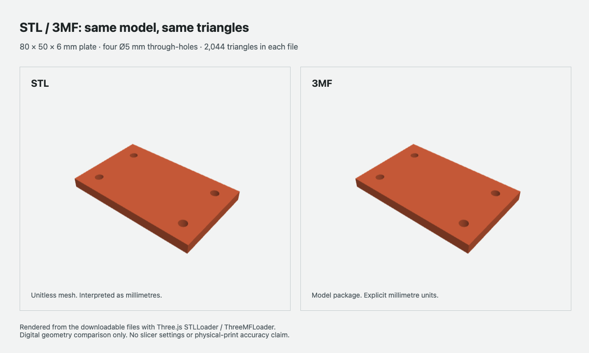
The two views show the downloadable meshes. The image illustrates their shape; it cannot verify a material assignment or a manufactured dimension. The report includes native geometry/export checks and a separate Trimesh 3MF-reader comparison. It does not report a slicer compatibility test or a physical print test.
Receiving checklist before you print
- Identify the file's purpose. Ask for model-only data or a slicer project, and record the source revision, exporter and application version.
- Confirm the receiving workflow. Check support for the model format, required extensions and any vendor-specific project data. Do not ignore missing-property warnings just because the shape appears.
- Check scale and placement. Measure a known dimension, confirm object count and review orientation, transforms and build-plate placement.
- Inspect materials and properties. Compare object or region assignments with the handoff note, then map them to the actual materials and printer tools. A preview color is insufficient evidence.
- Review settings and sliced layers. Confirm the printer profile, layer height, walls, infill and supports for the intended job. Look for missing thin features, closed holes and unintended material changes.
- Save and reopen the accepted project. Check the settings and assignments again in the intended application. Keep the source geometry and revision separately for later design changes.
- Recalculate the estimate after slicing. Use the receiving slicer's grams and time in the 3D printing cost calculator. A project from another machine is not a verified time or material estimate for yours.
Conversion and Studio export limits
Will STL to 3MF conversion recover missing information?
Only information supplied during conversion can be added. You can assign units, organize objects or add supported properties, but conversion cannot infer the original material intent, CAD parameters or slicer setup from triangles alone. Keep the source STL and record the conversion settings.
What can be lost when exporting 3MF as STL?
STL does not standardize the 3MF unit declaration, property resources or slicer project settings. Exporters also differ in which objects, transforms and generated structures they include. Reopen the resulting STL, check the intended geometry, and send units and print requirements separately. Retain the original 3MF project if you need its working state.
Does SKY-001 Studio export 3MF?
Studio exports STEP, STL, GLB and design JSON. The 3MF download on this page is a comparison-only asset, not a Studio export option. Use the dimensioned design-brief example to specify an inspectable model, and the text-to-CAD workflow to understand the independent product's scope and supported outputs.
Sources and scope of review
- 3MF Consortium: Core Specification & Reference Guide, version 1.4.0. Primary authority for packaging, model units, metadata, material resources, required extensions and document naming.
- Library of Congress: STL format family and binary STL. References for triangle geometry, metadata limits and incompatible binary color conventions.
- Marshall Burns: The StL Format, linked by the Library of Congress. Its format specification explicitly notes arbitrary coordinate units and no stored scale information.
- Prusa: saving projects as 3MF and export. Application-specific explanations of project saving versus STL geometry export.
Reviewed on 2026-10-29 against these documents and the linked digital verification record. This review does not certify a slicer, a printer, material performance or manufacturing accuracy.